(WOF) F1 tunnel hull building report

Dear rc friends,
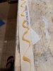
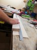
This is a new Wood Over Foam (WOF) F1 tunnel hull of my own design. As you will see in the photos the project is at an advanced stage because first I wanted to see if I could handle this new building technique. Overall, it is a wide and low profile (the height of the tunnel is 2 cm) design which adopts a number of characteristics from other designers of rc f1 hulls (see e.g. Jerry Dunlap (WOF), Dirk Jan (Cosy and Cosy T800), F1madness79, Zipkits G30 and others) and also from real F1 boats (e.g. the air steps or the center keel). I hope that this design will make the hull stable at cornering and less prone to flipping (due to less amount of air under the hull), but this is something that I will see in practice; maybe I am wrong :confused: who knows ;).
The specs of the model are:
- Total length: ~73 cm,
- Beam: 32 cm,
- Sponsors: length 70 cm, width 7 cm with air pads at the bow,
- Running pads: dead rise angle 11 degrees, width 4cm with 2 air steps,
- Center section: length 57.5 cm, width 18 cm with a center keel and an air step,
- Outboard: DIY bullet outboard,
- Engine: 3674, 2200 kv,
- Esc: 150 Amp, Flycolor
- Lipo: 4S-5S
- Propeller : I may start with a 40mm 1.4 pitch.

IMG_20221022_121328.jpg


IMG_20221022_120041.jpg


IMG_20221022_120139.jpg


IMG_20221022_120100.jpg


IMG_20221022_120105.jpg


IMG_20221022_120301.jpg


IMG_20221022_120114.jpg


IMG_20221022_120021.jpg


IMG_20221022_120123.jpg


IMG_20221022_120252.jpg
 
Wow, just like that you show this awesome and very advanced tunnel hull [emoji3][emoji106].
I like the features you insert in this design, such as the fins on top of the sponson fronts (don't know the proper name?). Also the lower mid section, the air gaps in the sponson running surface and the integrated nose section.
The deadrise of 11 degrees is a great choice I think. My Cozy F1 uses 14 degrees and my T800 uses 8 degrees. Although 8 degrees on my T800 works great, I think a slightly bigger deadrise will reduce the lift.

The width of the hull sounds quite big in relation to the length. I personally like that look, but the tunnel surface becomes somewhat bigger.

I'm really interested in how you used the WOF technique. Do you have some photos of shaping the foam? I guess you used a hot wire foam cutter?

I keep a close look on this topic. I think it will be a great performing hull [emoji108]
 
Thank you very much Jan :thumbsup:!!
I ve studied a lot both yours and Jerry Dunlap's plans and their related articles (he has written a number of very nice articles in rc magazines explaining his builds).

- For the deadrise angle I followed your advise that works fine, even if more wof plans I ve seen have bigger deadrise angle.

-
The width of the hull sounds quite big in relation to the length. I personally like that look, but the tunnel surface becomes somewhat bigger.

Yes it is a wide hull and I also like this looks. I borrowed this feature from JD's design who makes his hulls somewhat wider than the average. Let's see if the shallower tunnel will counteract the bigger surface.

- Now let me share with you the wof method I used:

2 top view templates are glued to the foam:
IMG_20220828_070804.jpg


I use a hot wire foam cutter to cut the foam following the templates. I also cut the inner sponsor former, the sponsor transom and the outside (non-running) sponsor former

IMG_20220828_105044.jpg


IMG_20220829_180153.jpg


Next I glue foam and wood with a gorrila glue (polyertherne glue which expands 3 times its volume)
IMG_20220829_182927.jpg


IMG_20220830_065549.jpg

The glue cures faster with water
IMG_20220830_072336.jpg


IMG_20220830_073133.jpg

I put a lot of weight on sponsor on a perfectly straight surface
IMG_20220830_073147.jpg

Before glueing
IMG_20220830_065618.jpg


IMG_20220830_070641.jpg
 
And now the magic, the most fun part of the build. The wire touches the inner and outer sponsor formers and you just move it forward cutting the foam nice and smoothly
IMG_20220830_144327.jpg

The main body of the sponsor is ready
IMG_20220830_145427.jpg


IMG_20220830_145434.jpg


Next post I ll show you the rest of the sponsor build.
 

Bijlagen

  • IMG_20220901_163106.jpg
    IMG_20220901_163106.jpg
    154,1 KB · Weergaven: 120
Very good explanation Dim, I start to understand the process.
If you have an edge or step over the length of the sponson (longitudinal) you have to cut the layers separately and glue them together. I guess you did that, if I look at your photos closely?

Regarding the tunnel width and height. That is an interesting topic.
I guess the lift of the tunnel is decided by the amount of air getting trapped underneath. Because the tunnel surface is rectangle: more length than width, the trapped air volume will reduce more than the gap reduction (due to lower tunnel) at the transom. It should result in less lift [emoji106].

By the way, will your transom be placed back as in the photo with the outboard? That is an interesting layout.
 
Because the tunnel surface is rectangle: more length than width, the trapped air volume will reduce more than the gap reduction (due to lower tunnel) at the transom. It should result in

That makes sense Jan. Let's see in practice :).

the way, will your transom be placed back as in the photo with the outboard?

Yes this will be the set up. I was thinking that the outboard is way too long moving the center of gravity to the transom. Thus I moved the transom 3 cm to the front but I retained the bottom of the center section. I did this so as to have a few cm more running surface during acceleration which may possibly help to improve the direction ality of the hull.

If you have an edge or step over the length of the sponson (longitudinal) you have to cut the layers separately and glue them together. I guess you did that, if I look at your photos closely?

That is correct Jan :thumbsup:. Using balsa and ply for plating you have a strong and relatively light running pad (this term is used by JD).
I upload the rest of photos from the build of the sponsors to see the process.

Plating the bottom of the sponsor with a 1 - 1,5 mm ply.
IMG_20220906_184452.jpg


I use a 3X5mm stringer from tiglio wood (it is hard, light and it bends relatively easy)
IMG_20220901_172652.jpg


I beveled the tiglio stringer carefully to make the right angle
IMG_20220906_190001.jpg


Then i glue the foam with gorrila glue (I like this glue for wood - foam because it expands itself and fills the empty spaces between the foam and the wood making a nice solid piece. You have to apply a thin layer and apply pressure because as it expands it may ruin your construction. Υου also have to wet one of the surface, because the glue cures with water.)
IMG_20220901_173108.jpg


IMG_20220902_060536.jpg


I use the hot wire to cut the foam + light sanding
IMG_20220901_204256.jpg


And this how you change the deadrise angle of the running pad. It is a relatively easy process and very fun. It is funny how stress relief is to cut foam with hotwire:D
.
IMG_20220901_204315.jpg


Checking its weight
IMG_20220902_060838.jpg
 

Bijlagen

  • IMG_20220902_055145.jpg
    IMG_20220902_055145.jpg
    144,6 KB · Weergaven: 116
Making the steps.
Just to notice that I positioned the steps by copying the real f1 boats. The 1st step is at the 25% from the sponsor's bow and the second at 25% from the sponsor's transom. I really don t know if it will work in scale but I guess we will find out soon.

I also used a 3mm ply for the inner side of the sponsor which forms the "the strakes" and the "air spoiler" exactly like cosy T800 (not shown in the photos below).

2 mm balsa stripe to make the second step
IMG_20221015_071703.jpg


Then another 2 mm stripe for the first step
IMG_20221015_074437.jpg


See the tiglio piece at the end of the step
IMG_20221015_071630.jpg


Sanding
IMG_20221015_084308.jpg


Trying to make them as symmetrical as possible before plating
IMG_20221015_101448.jpg


IMG_20221015_101515.jpg


Applying putty at the right and left sides of the stepped running pad for 3 reasons. 1. fill the gaps, 2. Bond the structure and 3. Make the balsa side more stiff.
IMG_20221016_121007.jpg


Rigth and left sides of the running pad are also laminated using a fiberglass tape. I chose a tape because it doesn't fray and you can handle it more easily. Plus it is thick enough ( approx 200 gr) to protect these surfaces.

IMG_20221017_045212.jpg


IMG_20221015_074451.jpg


Lastly, I use a 4X4mm tiglio stringer to make the "strakes" at the outside of the sponsor. I filled the rest of the outside area with balsa (not shown) in the photo.
IMG_20221015_102030.jpg


The tiglio stringers add weight but also make the structure solid. The same holds for the two layers of ply at the bottom in order to make the steps or the 3mm inner former. But I believe that along with a 110 gr fiberglassing the sponsors will be strong enough to handle a 3674 motor.

PS. In f1 rc tunnels I see almost no steps except for the big scale gas tunnels (1.3 to 1.5 meters). Probably they are useless in small scale or the cost benefit trade off is quite small. Anyway, I like this feature and I had fun constructing it and that is what counts afterall.
 
Very clean and precise build [emoji108] It will make it easier to make a nice and smooth finish, as well as it will improve performance if all angles and dimensions match.

Regarding the air gaps: the power to weight ratio is so high in rc Tunnels, that the hull will easily run almost entirely loose from the water. It might help in the corners? Anyway, they look nice [emoji41]
 
What a clean build [emoji7]
I really like the sponson type ,and are very excited about the shape .
Really hope to that they perform the way they look.
 
Thank you both guys! I tried to make it as clean as possible to avoid unnecessary sanding later. I also decided to use puty in wood imperfections before fiberglassing.

@Dirk Jan i totally agree with your explanation for the steps. They may also have a small beneficial effect on acceleration.

@Tamiya1970 I really hope the same. Also the wsb f1 tunnels are a benchmark for rc f1 designing. I think that I ve seen the step in the center section in one of the wsb f1 models
 
Center section construction (part 1)

Center section building is relatively straightforward and follows the building technique of Cosy F1.
Nonetheless it has two new aspects: a) a 9mm cf tube that connects the two sponsors and of course the center secrion in order to increase the overall hull rigidity and b) an incorporated nose of the cowl so as to have a nice smooth center section keel.

Below you can find some photos:

IMG_20220917_065810.jpg


IMG_20220918_074731.jpg


IMG_20220917_071800.jpg


IMG_20220917_073639.jpg


IMG_20220917_080351.jpg


IMG_20220918_072950.jpg


IMG_20220925_175706.jpg
IMG_20220918_072935.jpg


IMG_20220925_175345.jpg

IMG_20220925_191819.jpg
 
Very interesting to see and nice work. The tunnel section is made out of 3 separate parts, looking at your photos.

Looking forward to the next build steps!
 
I love the lines of this F1 design. The hull is low profile [emoji106]. Neat work, looking forward to your progress.
 
Back
Top