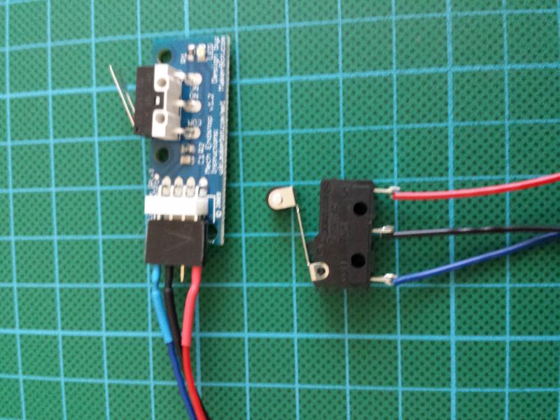
Switch requirements
You want a normally closed (NC) switch. Meaning you need a switch which connects two poles when not triggered. (A single pole double throw (SPDT) switch will work, if you wire up to the NC side of the switch -- ignore the NO pin)
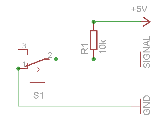
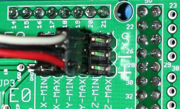
Switch wiring
When the switch is off (like in the schematic above), it connects signal to ground. When the switch is triggered, the ground connection is cut and the signal is connected to 5v through the pull up resistor.
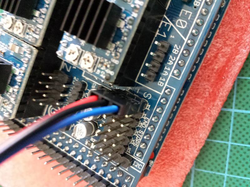
Make sure you keep the wires away from the motor leads and / or used screened cable as it is easy to pick up enough noise to get false triggering. [4]
Note: if you use Teacup or Sprinter firmware, then resistor R1 and the connection to 5V are obsolete. The Arduino ATmega has internal pullup resistors which can be turned on in the firmware using the USE_INTERNAL_PULLUPS flag in config.h for Teacup firmware or ENDSTOPPULLUPS in configuration.h for Sprinter and Marlin firmware.
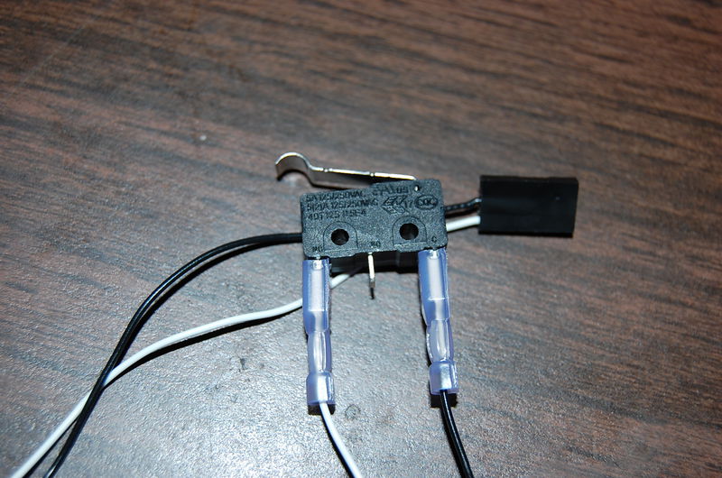
Using the internal pullup resistors eliminates the need for external resistors, which simplifies the wiring. If internal pullup resistors are used the switch can simply be connected to the signal and ground pins. Reportedly sometimes the internal pullup resistors have a large tolerance which can in rare cases cause issues. If you are having problems first double check that your wiring is correct and confirm that your firmware is configured correctly before deciding you may have bad internal pullup resistors.
") .
.
") wat uiteraard niet lukte.
wat uiteraard niet lukte.