'How to' DX6i backlight mod.
auteur: "theflyingeagle"
Let op!!
Dit is een risicovol klusje, doe je het niet goed heb je een redelijk probleem… de garantie vervalt zodra je de zender open maakt.. (Edit: De garantie vervalt niet bij openen v/d zender. Denk aan het afstellen van de veertjes van de sticks of het veranderen van 'mode'. Door de modificatie zelf, waarbij daadwerkelijk dingen worden verwijderd (folie) en veranderd (solderen), vervalt wèl de garantie. Helihabit)
Dit is ook toe te passen in andere zenders, hierbij moet je wel genoeg kennis van zaken hebben...
Bij 35Mhz zenders is het oppassen... de Inverter wekt een Frequentie op van ongeveer 200Hz, dit kan de zend module van de zender nadelig beïnvloeden..
Dus altijd controleren of het goed gaat....
Ook nadat de zender is open geweest altijd een Range Check uitvoeren!!!
U bent gewaarschuwd.
Benodigdheden:
• El folie 112x87 mm (wit) conrad bestel nummer 184084 – 89 € 8,06 Edit: 112x87 Blauw €8.22
• EL Inverter conrad bestel nummer 184005 – 89 € 5,-
• Beetje koperdraad, tin en krimpkous
Gereedschap:
• Kruis schroeven draaiers 1 grote om de zender open te maken en 1 kleinere voor de printplaat schroefjes.
• Kniptangetje
• Soldeerbout

Knip 4 draden in de juiste lengte af en vertin de uiteindes, soldeer ze dan aan de inverter en het EL folie zoals op de tekening staat (word met de inverter mee geleverd).

Het is wel zo slim om voor de plus een rood draadje te pakken en voor de min een zwarte, dan is het verschil iets beter te zien en voorkomt dat je het per ongeluk verkeerd gaat doen.
Even testen of alles werkt....

Daarna schroef je de zender open, denk dat iedereen de schroefjes wel kan vinden….
Dan zie je verschillende printplaten zitten, de grootste mag los en eventueel ook van de scroll knop.
De grote print zit vast met 4 schroeven op de hoeken, de andere 2 zijn voor het LCD en die mogen er ook uit
Maak het flatcable'tje ook los van het LCD zodat je het LCD er uit kan halen.

Het bruine stukje kunstof kan naar beneden worden geschoven, even de nagels er tussen en hij is los.

EDIT: de volgende stap hoeft niet! voor een betere verlichting kan je deze wel uitvoeren maar het is dus niet nodig!
Nu moet er een folie van het LCD worden gehaald, dit is best oppassen geblazen want er zitten er 3 op.
Allen de eerste 2 moeten er af, dit is een doorzichtig folie tje en een zilveren.
Haal je er meer af dan die 2 heb je de polariserende te pakken en dan is je LCD afgeschreven… en zie dan maar aan een nieuwe te komen.

Als dat gedaan is kan je het licht folie op maak knippen, dat kan gewoon met een schaar. Tip: gebruik het zilveren folie als mal dan knip je exact het juiste formaat uit, en recht.

Daarna plak je met wat plakband het lichtfolie achter op het LCD, let wel op dat je de licht gevende kant tegen het LCD plakt, dus test hem eerst even voor je alles inbouwd!
Nu moet er een folie van het LCD worden gehaald, dit is best oppassen geblazen want er zitten er 3 op.
Allen de eerste 2 moeten er af, dit is een doorzichtig folie tje en een zilveren.
Haal je er meer af dan die 2 heb je de polariserende te pakken en dan is je LCD afgeschreven… en zie dan maar aan een nieuwe te komen.

Dan is het weer even pielen om het weer in de zender te krijgen….
Maar nu moet het nog een voeding hebben, nu wil ik geen extra schakelaar er in..
Dus heb ik het afgetapt van de hooft schakelaar, dat is vrij simpel even meten en je weet wat.

Edit(Helihabit): binnenaanzicht na backlight mod. De inverter heb ik vastgezet met dubbelzijdige foamtape
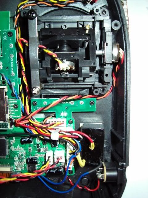
EL-Inverter▬▬▬▬▬▬▬▬▬▬ ↑
Daarna is het even de boel vast zetten en checken, en dan kan de zender weer dicht en heb je een Spectrum zender met Backlight!

In het echt ziet het er meer wit uit dan op de foto...
Maar je kan ook een andere kleur nemen, ik vond dit wel netjes..
Let op! Het in praktijk brengen van onderstaande handleiding is op eigen risico.
Dit menu niet gebruiken als bij "Monitor" de stickposities in orde zijn en er een datumsticker in het batterijenvak aanwezig is.
Persoonlijk heb ik op geen enkele andere functie van de zender een neveneffect kunnen vinden na het 'calibratie menu' te hebben geopend en de sticks te hebben gecalibreerd/uitgelezen.
'Calibratie' menu geplaatst door "Helihabit"
Ensure that "AIL D/R", "FLAP/GYRO", "ELEV D/R", "GEAR/F MODE", "RUDD D/R" are in 0 position (UP) and MIX/TH HOLD is in 1 position (DOWN).
1. Turn OFF your Spectrum DX6i
2. Push both dx6i horizontal trims at the same time to the direction of POWER switch. (Push Left trim to the right and right trim to the left)
Hold them so and now turn ON your dx6i.
You should see version information if you still hold trims.
If you release trims then dx6i shows calibration summary menu.
Now it gets interesting.
* Flip the AIL D/R switch down and you are in the UP position calib. menu. Move your sticks to set new UP position values. System shows only highest values. To get summary menu just flip the AIL D/R switch up.
* Flip the FLAP/GYRO switch down and you are in the MIDDLE position calib.menu. In this menu you can set new middle values for sticks
to get summary menu just flip the FLAP/GYRO switch up.
* Flip the ELEV D/R switch down and you are in the DOWN position calib.menu. In this menu you can set new down values for sticks. System shows only lowest value to get summary menu just flip the ELEV D/R switch up.
* If you flip the MIX/TH HOLD to UP and DOWN (LCD goes blank in UP position) then original calib. data is reloaded.
SAVING NEW CALIB. DATA - in the summary menu flip the MIX/TH HOLD to UP (screen is blank) and press Roller.
It will beep few times and will go in to standard SETUP MONITOR menu.
* SW TEST (switch test) - in the summary menu flip the MIX/TH HOLD to UP (screen is blank) and flip the GEAR/F MODE to DOWN
Doe je voordeel
Change Mode for your Spectrum DX6i Radio From MODE 2 to MODE 1
Disclaimer:
Before you begin, please keep in mind that any of this modification probably invalidate your warranty, any damage caused to your Tx following these instructions is your responsability, all steps are reversible but you can not guarantee that you wont loose a screw or break some tiny plastic part, so be very carefull.
Change the software.
To enter the hidden menu:

Go to the COPY/RESET menu inside the SETUP LIST.

Choose RESET. (DRAGONUS is the name i have assigned to my model 1 in the Tx memory)

When you are asked yes / no highlight the "list" button in the top right.

After this switch the AIL D/R switch at the top right from position 1 to 0 two or three times..

after this procedure the transmitter should open the menu to change mode.

Choose your mode with the dial and push the dial to accept.
Change the spring from the right stick to te left.
Tools you will need:

I reccomend you use your styrofoam packaging to protect your transmitter from scratches.

1.- Remove the 4 "AA" batteries from the batteries compartement.
2.- Remove the back part of the transmitter case, unscrewing the 6 phillips head screws.

3.- Before you remove this 3 connectors that connect both parts, mark with a "sharpie" pen, to reconnect them as they need to be.

4.- Untight this 2 screws and remove the friction plate.

5.- I used my RC wrench to remove this nut (4mm hex)

6.-Screw into the new position (some people doesnt use this friction plate so steps 5 thru 8 can be ommited).

7.- Use silicon oil to lube the plastic were the friction plate makes contact.

8.- Screw the friction plate as the picture shows, black screw goes almost all the way and the silver screw is to adjust the friction feel that you like the most, move the throttle stick and adjust as desired.

9.- Remove the right stick spring (be carefull not to loose it or bent it).

10.- Remove this plastic part.

11.- This 3 pins needs to be removed from Right Stick to be put in the Left Stick.

12.- Use a bent nose pliers like the picture and be very carefull since there is very little space.

13.- Remove one by one and place in the other stick, the position is the same but remember that the stick is rotated 180°.

14.- Twist a little first to make it easy to pull out.

15.- Use a 2mm hex screw remover to remove the right stick from the front half case, this are just 4 screws.

16.- Remove the little plastic part that keeps the spring tensioner in position, you need to use a small screwdriver to help to push it out from the inside, reassemble the right stick and make this same steps 15 and 16 to put in the left stick.

17.- Reattach the spring into position, put the tension adjusting screw into position and adjust the same tension as the horizontal stick.
18.- Reconnect all 3 connector to the printed circuit (notice they original position) reassemble both transmitter case parts using the 6 phillips head screws.

19.- OK now you have a new MODE 1 Brand New Transmitter.
CREDITS:
Software Procedure:
Hardware Procedure, Pictures and Text:
Max3Design
Mocht je de trimknoppen willen vervangen:
• Kunststof 3D print Spektrum DX6i trimmer
• CNC aluminium trimknoppen
'How to' DX6i backlight mod.
auteur: "theflyingeagle"
Let op!!
Dit is een risicovol klusje, doe je het niet goed heb je een redelijk probleem… de garantie vervalt zodra je de zender open maakt.. (Edit: De garantie vervalt niet bij openen v/d zender. Denk aan het afstellen van de veertjes van de sticks of het veranderen van 'mode'. Door de modificatie zelf, waarbij daadwerkelijk dingen worden verwijderd (folie) en veranderd (solderen), vervalt wèl de garantie. Helihabit)
Dit is ook toe te passen in andere zenders, hierbij moet je wel genoeg kennis van zaken hebben...
Bij 35Mhz zenders is het oppassen... de Inverter wekt een Frequentie op van ongeveer 200Hz, dit kan de zend module van de zender nadelig beïnvloeden..
Dus altijd controleren of het goed gaat....
Ook nadat de zender is open geweest altijd een Range Check uitvoeren!!!
U bent gewaarschuwd.
Benodigdheden:
• El folie 112x87 mm (wit) conrad bestel nummer 184084 – 89 € 8,06 Edit: 112x87 Blauw €8.22
• EL Inverter conrad bestel nummer 184005 – 89 € 5,-
• Beetje koperdraad, tin en krimpkous
Gereedschap:
• Kruis schroeven draaiers 1 grote om de zender open te maken en 1 kleinere voor de printplaat schroefjes.
• Kniptangetje
• Soldeerbout

Knip 4 draden in de juiste lengte af en vertin de uiteindes, soldeer ze dan aan de inverter en het EL folie zoals op de tekening staat (word met de inverter mee geleverd).

Het is wel zo slim om voor de plus een rood draadje te pakken en voor de min een zwarte, dan is het verschil iets beter te zien en voorkomt dat je het per ongeluk verkeerd gaat doen.
Even testen of alles werkt....

Daarna schroef je de zender open, denk dat iedereen de schroefjes wel kan vinden….
Dan zie je verschillende printplaten zitten, de grootste mag los en eventueel ook van de scroll knop.
De grote print zit vast met 4 schroeven op de hoeken, de andere 2 zijn voor het LCD en die mogen er ook uit
Maak het flatcable'tje ook los van het LCD zodat je het LCD er uit kan halen.

Het bruine stukje kunstof kan naar beneden worden geschoven, even de nagels er tussen en hij is los.

EDIT: de volgende stap hoeft niet! voor een betere verlichting kan je deze wel uitvoeren maar het is dus niet nodig!
Nu moet er een folie van het LCD worden gehaald, dit is best oppassen geblazen want er zitten er 3 op.
Allen de eerste 2 moeten er af, dit is een doorzichtig folie tje en een zilveren.
Haal je er meer af dan die 2 heb je de polariserende te pakken en dan is je LCD afgeschreven… en zie dan maar aan een nieuwe te komen.

Als dat gedaan is kan je het licht folie op maak knippen, dat kan gewoon met een schaar. Tip: gebruik het zilveren folie als mal dan knip je exact het juiste formaat uit, en recht.

Daarna plak je met wat plakband het lichtfolie achter op het LCD, let wel op dat je de licht gevende kant tegen het LCD plakt, dus test hem eerst even voor je alles inbouwd!
Nu moet er een folie van het LCD worden gehaald, dit is best oppassen geblazen want er zitten er 3 op.
Allen de eerste 2 moeten er af, dit is een doorzichtig folie tje en een zilveren.
Haal je er meer af dan die 2 heb je de polariserende te pakken en dan is je LCD afgeschreven… en zie dan maar aan een nieuwe te komen.

Dan is het weer even pielen om het weer in de zender te krijgen….
Maar nu moet het nog een voeding hebben, nu wil ik geen extra schakelaar er in..
Dus heb ik het afgetapt van de hooft schakelaar, dat is vrij simpel even meten en je weet wat.

Edit(Helihabit): binnenaanzicht na backlight mod. De inverter heb ik vastgezet met dubbelzijdige foamtape
EL-Inverter▬▬▬▬▬▬▬▬▬▬ ↑
Daarna is het even de boel vast zetten en checken, en dan kan de zender weer dicht en heb je een Spectrum zender met Backlight!

In het echt ziet het er meer wit uit dan op de foto...
Maar je kan ook een andere kleur nemen, ik vond dit wel netjes..
Let op! Het in praktijk brengen van onderstaande handleiding is op eigen risico.
Dit menu niet gebruiken als bij "Monitor" de stickposities in orde zijn en er een datumsticker in het batterijenvak aanwezig is.
Persoonlijk heb ik op geen enkele andere functie van de zender een neveneffect kunnen vinden na het 'calibratie menu' te hebben geopend en de sticks te hebben gecalibreerd/uitgelezen.
'Calibratie' menu geplaatst door "Helihabit"
Ensure that "AIL D/R", "FLAP/GYRO", "ELEV D/R", "GEAR/F MODE", "RUDD D/R" are in 0 position (UP) and MIX/TH HOLD is in 1 position (DOWN).
1. Turn OFF your Spectrum DX6i
2. Push both dx6i horizontal trims at the same time to the direction of POWER switch. (Push Left trim to the right and right trim to the left)
Hold them so and now turn ON your dx6i.
You should see version information if you still hold trims.
If you release trims then dx6i shows calibration summary menu.
Code:
---T---A---E---R
U 915 956 947 956
M 472 504 508 544
D 043 067 082 060
U 915 956 947 956
M 472 504 508 544
D 043 067 082 060
T - THRO stick
A - AILE stick
E - ELEV stick
R - RUDD stick
U - up position of stick
M - middle position of stick
D - down position of stick
A - AILE stick
E - ELEV stick
R - RUDD stick
U - up position of stick
M - middle position of stick
D - down position of stick
Now it gets interesting.
* Flip the AIL D/R switch down and you are in the UP position calib. menu. Move your sticks to set new UP position values. System shows only highest values. To get summary menu just flip the AIL D/R switch up.
* Flip the FLAP/GYRO switch down and you are in the MIDDLE position calib.menu. In this menu you can set new middle values for sticks
to get summary menu just flip the FLAP/GYRO switch up.
* Flip the ELEV D/R switch down and you are in the DOWN position calib.menu. In this menu you can set new down values for sticks. System shows only lowest value to get summary menu just flip the ELEV D/R switch up.
* If you flip the MIX/TH HOLD to UP and DOWN (LCD goes blank in UP position) then original calib. data is reloaded.
SAVING NEW CALIB. DATA - in the summary menu flip the MIX/TH HOLD to UP (screen is blank) and press Roller.
It will beep few times and will go in to standard SETUP MONITOR menu.
* SW TEST (switch test) - in the summary menu flip the MIX/TH HOLD to UP (screen is blank) and flip the GEAR/F MODE to DOWN
Doe je voordeel
Change Mode for your Spectrum DX6i Radio From MODE 2 to MODE 1
Disclaimer:
Before you begin, please keep in mind that any of this modification probably invalidate your warranty, any damage caused to your Tx following these instructions is your responsability, all steps are reversible but you can not guarantee that you wont loose a screw or break some tiny plastic part, so be very carefull.
Change the software.
To enter the hidden menu:
Go to the COPY/RESET menu inside the SETUP LIST.
Choose RESET. (DRAGONUS is the name i have assigned to my model 1 in the Tx memory)
When you are asked yes / no highlight the "list" button in the top right.
After this switch the AIL D/R switch at the top right from position 1 to 0 two or three times..
after this procedure the transmitter should open the menu to change mode.
Choose your mode with the dial and push the dial to accept.
Change the spring from the right stick to te left.
Tools you will need:
I reccomend you use your styrofoam packaging to protect your transmitter from scratches.
1.- Remove the 4 "AA" batteries from the batteries compartement.
2.- Remove the back part of the transmitter case, unscrewing the 6 phillips head screws.
3.- Before you remove this 3 connectors that connect both parts, mark with a "sharpie" pen, to reconnect them as they need to be.
4.- Untight this 2 screws and remove the friction plate.
5.- I used my RC wrench to remove this nut (4mm hex)
6.-Screw into the new position (some people doesnt use this friction plate so steps 5 thru 8 can be ommited).
7.- Use silicon oil to lube the plastic were the friction plate makes contact.
8.- Screw the friction plate as the picture shows, black screw goes almost all the way and the silver screw is to adjust the friction feel that you like the most, move the throttle stick and adjust as desired.
9.- Remove the right stick spring (be carefull not to loose it or bent it).
10.- Remove this plastic part.
11.- This 3 pins needs to be removed from Right Stick to be put in the Left Stick.
12.- Use a bent nose pliers like the picture and be very carefull since there is very little space.
13.- Remove one by one and place in the other stick, the position is the same but remember that the stick is rotated 180°.
14.- Twist a little first to make it easy to pull out.
15.- Use a 2mm hex screw remover to remove the right stick from the front half case, this are just 4 screws.
16.- Remove the little plastic part that keeps the spring tensioner in position, you need to use a small screwdriver to help to push it out from the inside, reassemble the right stick and make this same steps 15 and 16 to put in the left stick.
17.- Reattach the spring into position, put the tension adjusting screw into position and adjust the same tension as the horizontal stick.
18.- Reconnect all 3 connector to the printed circuit (notice they original position) reassemble both transmitter case parts using the 6 phillips head screws.
19.- OK now you have a new MODE 1 Brand New Transmitter.
CREDITS:
Software Procedure:
Hardware Procedure, Pictures and Text:
Max3Design
Mocht je de trimknoppen willen vervangen:
• Kunststof 3D print Spektrum DX6i trimmer
• CNC aluminium trimknoppen
Laatst bewerkt:
 :twisted:. Als dat DN05:00 iets zegt over de software versie!?
")
") . Er zat ook track en trace bij, Donderdags om 5 uur geland op Schiphol, volgende dat 11 uur in Hilversum afgeleverd, super snel dus!!
. Er zat ook track en trace bij, Donderdags om 5 uur geland op Schiphol, volgende dat 11 uur in Hilversum afgeleverd, super snel dus!!